
This is an old revision of the document!
Table of Contents
Question: My Airmate is still with the previous USB configuration and they both receive the Program bus. Can they also receive the Auxilary send? How can I fix this?
Answer: Link: please follow the steps at this link
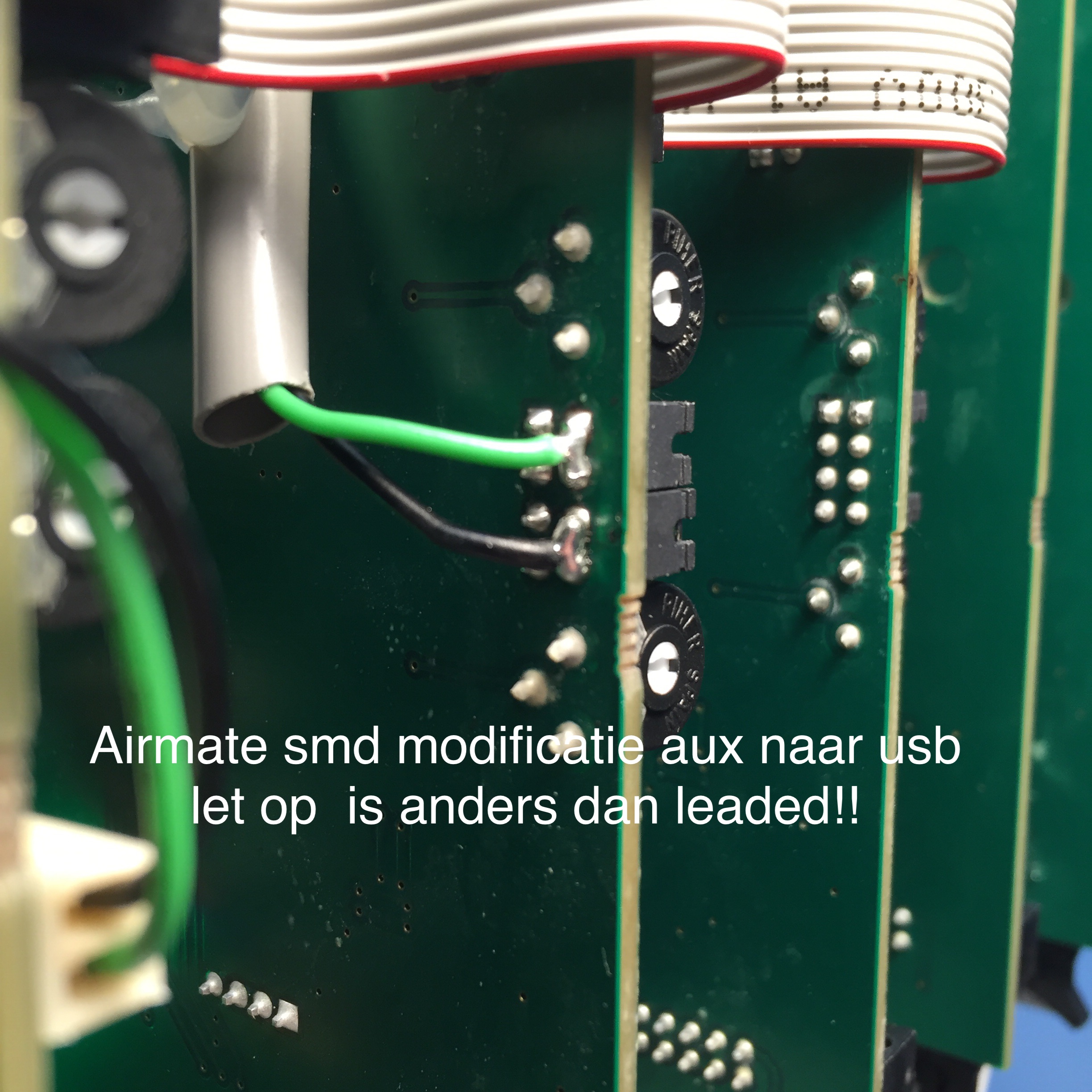
For latest models with SMD components (Version 4 or later)
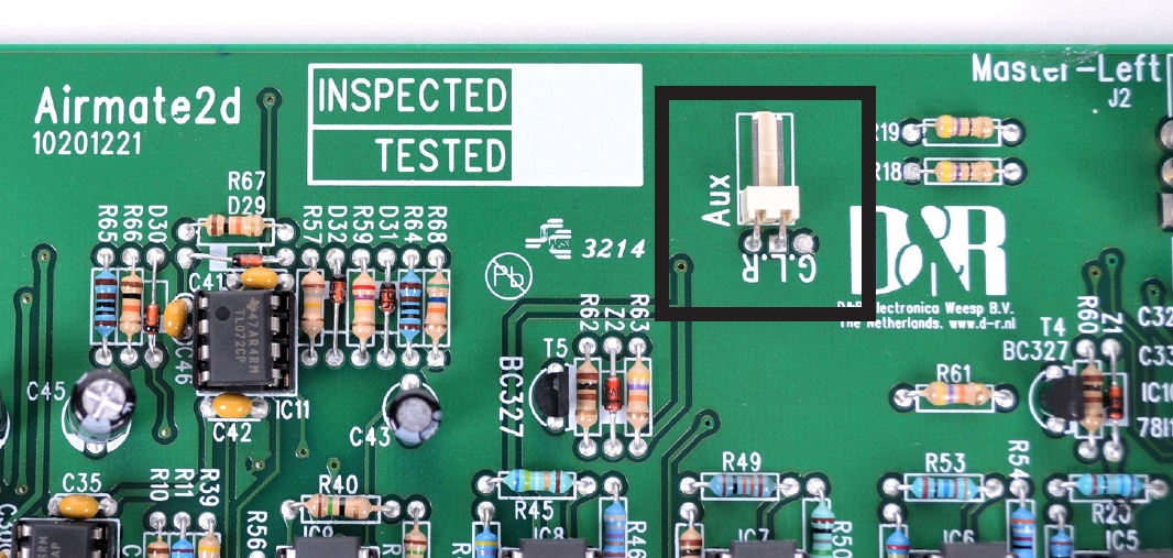
Place both Jumpers on the PCB's edge positions of the Jumper header.
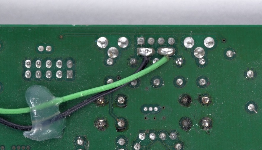
Solder 2 wires to this position of the Jumper headers.
Black has to be connected to Left and Green has to be connected to Right!
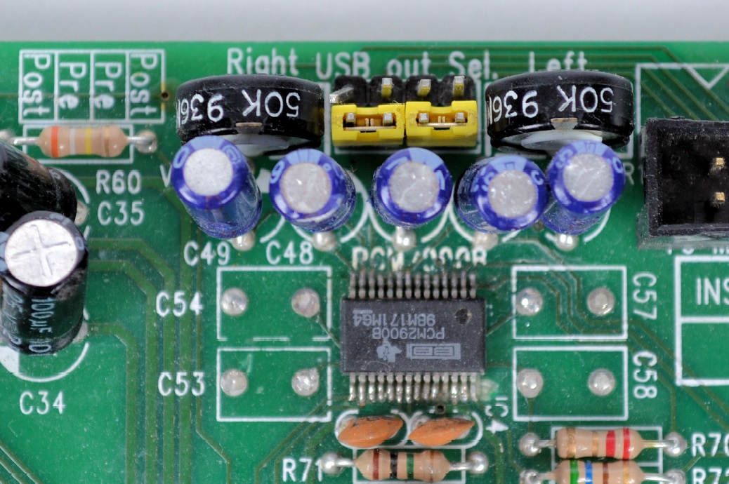
Connect the 2 Pin female connector to this male pcb connector or solder the wires to these pins.
Black has to be connected to Left and Green has to be connected to Right!
For older models with leaded components (Version 3 or earlier)
Place jumpers in this position
Solder 2 wires to this position of the Jumper headers.
Black has to be connected to Left and Green has to be connected to Right!
Connect the 2 Pin female connector to this male pcb connector or solder the wires to these pins.
Black has to be connected to Left and Green has to be connected to Right!
If your Left Master PCB doesn't have the 2 pin Auxilary connecter you can do it this way:
Place jumpers in this position
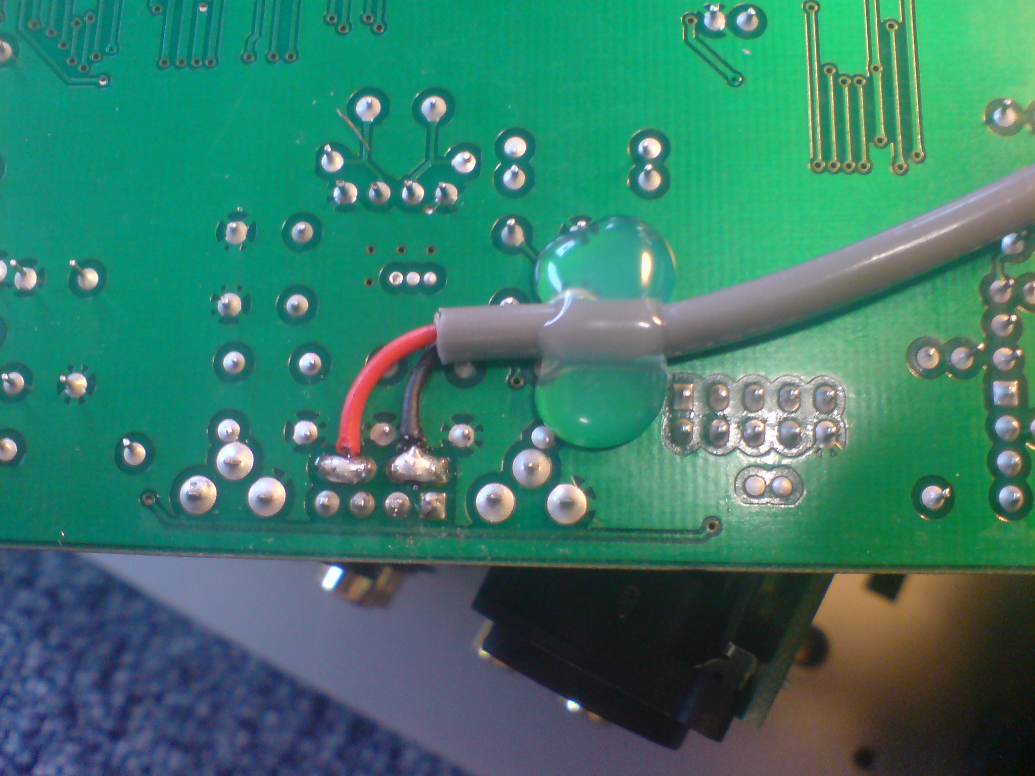
Solder 2 wires to this position of the Jumper headers.
Black has to be connected to Left and Red has to be connected to Right!
On the Master 2 (Left) PCB you'll find 2 resistors next to the Auxilary send RCA connector.
Solder the Red and Black wire to the points as in the example.